Welcome to ImageMap Support in oXygen


Table of Contents

Gear Pump - Exploded View
Drive shaft
Bushings
Gears
Drive Gear (Rotor)
Idler Gear
Ports
Suction Port
Pressure Port
Seals
Shaft Seal
Case Seal
Mounting Flange

Gear Pump - Exploded View

Exploded view diagram of a gear pump.

Exploded view diagram of a gear pump. Drive gear Idler gear Suction port Pressure port Shaft seal Mounting flange Drive shaft Bushings section Bushings section Bushings section Bushings section Case seal

Drive shaft

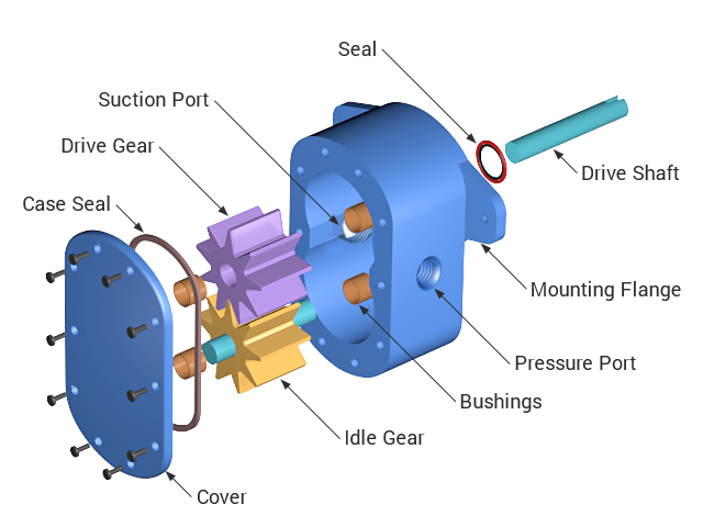
A drive shaft is a mechanical component for transmitting torque and rotation, usually used to connect other components of a drive train that cannot be connected directly because of distance or the need to allow for relative movement between them..

Bushings

A bushing, also known as a bush, is an independent plain bearing that is inserted into a housing to provide a bearing surface for rotary applications. The bushings in the gear pump provide a bearing surface for the drive gear and idler gear.

Gears

The gear pump uses two identical gears rotating against each other. One gear is driven by a motor and it in turn drives the other gear. Each gear is supported by a shaft with bushings on both sides of the gear.

Drive Gear (Rotor)

The drive gear in the gear pump is the gear that is driven by the motor.

Idler Gear

The idler gear is the gear that is driven by the drive gear .

Ports

Suction Port

The liquid enters in the pump through the suction port.

Pressure Port

The liquid leaves the pump through the pressure port (or discharge port).

Seals

Shaft Seal

This is a seal that is placed between the drive shaft and the main case of the gear pump.

Case Seal

The case seal is placed between the main case and the case cover.

Mounting Flange

Mounting Flange - The mounting flange is used to fix the pump on a support apparatus.